Wave determination of electron drift velocities in positive columns
B. A. Aničin i V. M. Babović · 1976
B. A. ANlČlN and V. M. BABOVIĆ
The propagation of guided electron plasma waves on drifting plasmas is accompanied with differences in wavenumber, attenuation and wave amplitude between the two waves travelling with and against the stream. The electron drift velocity can be determined both from the differences in wavenumber and wave amplitude. In addition, the asymmetry in wavenumber has led to a verification of the Lorentz expression for the drag coefficient.
Introduction
Electron waves travelling on a column of drifting plasma have different properties in the upstream and downstream directions. The difference stems from the Doppler effect introduced by the electron drift velocity. Although the impact of drift on upstream and downstream wavenumbers and group velocities was predicted theoretically by Trivelpiece and Gould as early as 1959, the effect was not subject to detailed experimental investigations, with the notable exception of a paper by Keržar and Weissglas (1965). The scarcity of observations of the asymmetry in wave properties is probably due to the fact that most authors have conducted standing wave measurements which yield unresolved arithmetic means of upstream and downstream wavenumbers and attenuation coefficients (Aničin et al. 1973).
The electron drift velocity induces upstream-downstream differences in
(a) the real part of the wavenumber ;
(b) the imaginary part of the wavenumber (attenuation effects) ;
(c) initial wave amplitudes.
Resolved attenuation measurements have been reported elsewhere (Aničin and Babović 1975). This paper deals with phenomena related to the real part of the wavenumber and initial wave amplitudes. The interpretation of the phase properties of electron waves leads to a verification of the Lorentz drag coefficient in dispersive media and was previously reported by the authors as a conference communication (Aničin and Babović 1974). Initial wave amplitude differences can be used to measure electron drift velocities (Babović and Aničin 1975).
All measurements have been conducted in the positive column of a low-pressure mercury vapour arc. Section 2 deals with the standard determination of drift velocity from arc current. The wave measurements and the interpretation of the upstream-downstream differences in the wavenumber in terms of the Lorentz coefficient are described in § 3. Section 4 deals with the determination of drift velocities from wave amplitude asymmetry.1
The electron drift velocity in the positive column of the mercury vapour arc
The simplest method to determine electron drift velocity is to derive it from the discharge current and electron density, using the relation
where is the cross section area of the positive column, the electronic charge and the electron concentration averaged by taking the number of electrons per unit length of positive column.
Previous experiments (Ilić and Aničin 1970) have shown that the ratio is approximately constant, in accordance with the theory of the positive column. With a plasma radius () these density data yield electron drift velocities listed in Table 1.
[TABLE]
Table 1
Electron drift velocity from the asymmetry in the real part of the wavenumbers
Experiments
The lay-out of the wave measurement set-up is shown in Fig. 1. The bounded drifting plasma is the positive column of a mercury vapour arc,
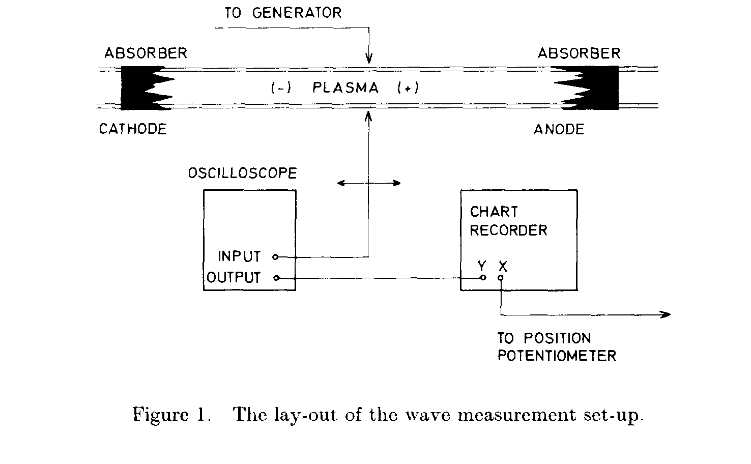
6 mm in radius and surrounded by a Pyrex glass tube 1.7 mm thick. Aquadag coatings are laid on both ends of the tube 75 cm apart, shaped as coronet absorbers to minimize reflections from the anode and cathode structures and avoid the superposition of waves travelling in both directions, which tend to mask the difference existing in pure upstream and downstream waves and yield unresolved arithmetic means of upstream and downstream wave-numbers (Aničin et al. 1973). The coaxial launching antenna, as described in Aničin et al. (1972) excites electron plasma waves modified by the finite radial extent of the plasma and the presence of the glass, at the angular frequency , . These waves are intercepted with a wire radial probe (5 mm long, with the tip 5 mm away from the glass) and the resulting voltage pulses are applied to the input of a sampling oscilloscope operated at constant sampling time. The oscilloscope output is connected to a chart recorder which registers a snapshot of the wave field at ., where z is the axial coordinate and t the time. A set of typical wave patterns is shown in Fig. 2. The parameter in the figure is discharge current, the vapour pressure is 0.161 Pa. The cathode is to the left of the
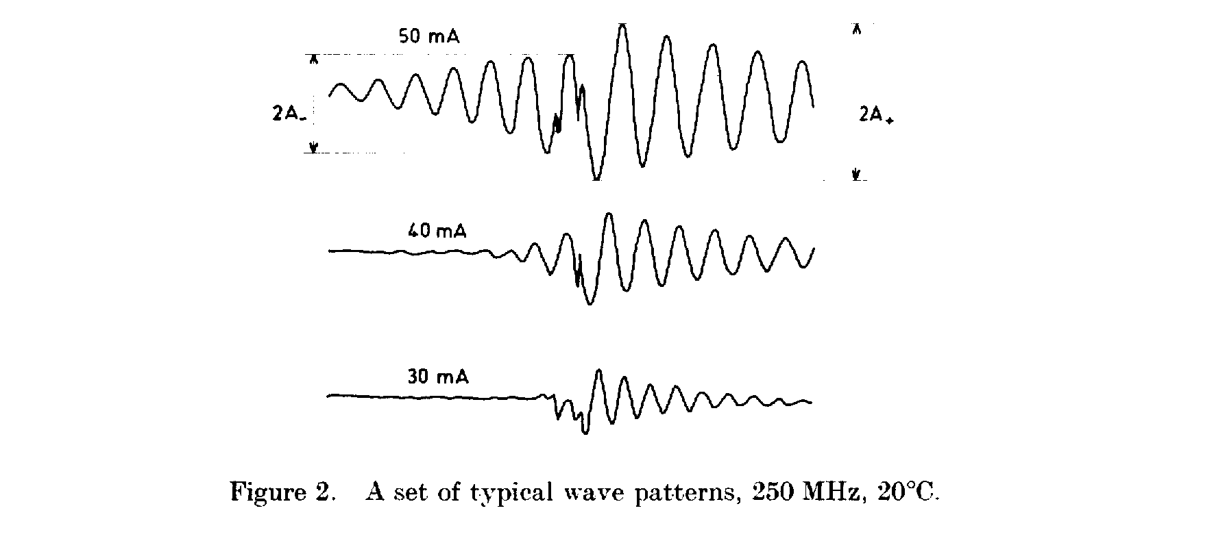
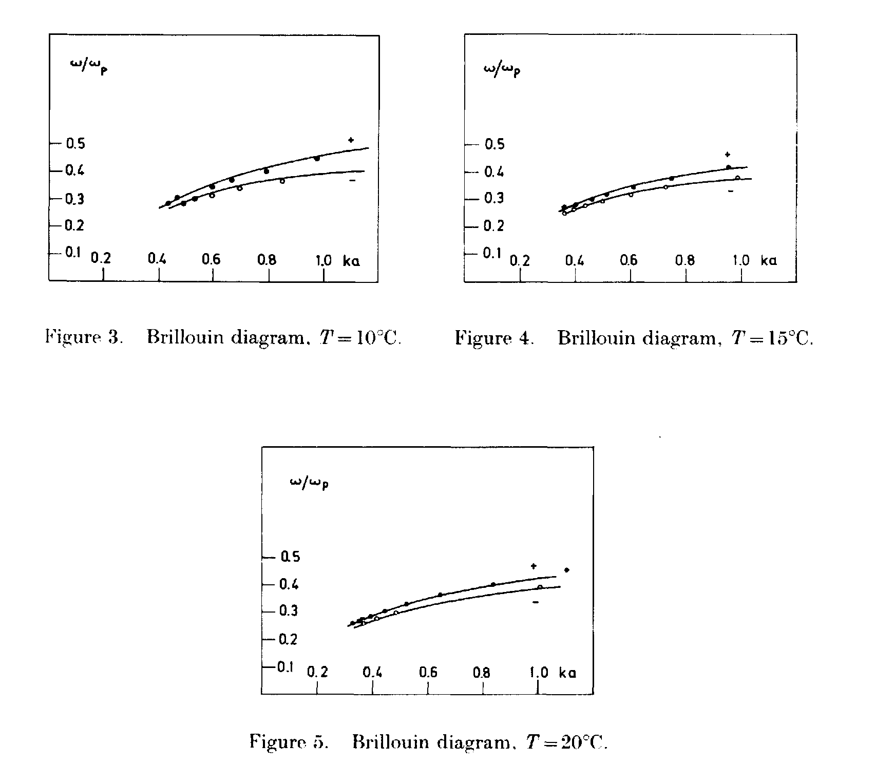
centrally located launcher, the anode is to the right. The wave pattern is clearly asymmetric and the difference in wavenumber, attenuation and initial amplitude apparent. The attenuation of waves on drifting plasmas has been dealt with elsewhere (Aničin and Babović 1975). All wave properties depend on vapour pressure and on discharge current. The dispersion relations (Brillouin diagrams, curves) for a drifting plasma can be obtained from such experimental records and are shown in Figs. 3, 4 and 5. The underlying numerical data are summarized in Table 2. The ( + ) sign refers to the downstream (anode oriented) wave whereas the ( - ) sign pertains to the upstream (cathode oriented) wave. The ordinate is normalized to the plasma frequency , the abscissa to the plasma radius a.
It should be noted that, although Fig. 2 and similar records have been made with the launcher halfway between the anode and cathode to demonstrate wave asymmetry, all final measurements of the wavenumber have been
[TABLE]
Table 2
made with the launcher at the appropriate end of the tube, to increase the number of discernible wavelengths and the accuracy in wavenumber determination.
Interpretation
Dispersion relations such as those shown in Figs. 3, 4 and 5 can be interpreted by two equivalent procedures :
(a) a vertical line is drawn at some k’ = const, and the drift velocity determined from the two Doppler shifted frequencies ω~+~’ and ω_’
where u is the drift velocity. This procedure was used by Keržar and Weissglas (1965) ;
(b) a horizontal line is drawn at some ω’ = const, (or ω/ωρ = const.) and the difference in wavenumber determined, which is more in the spirit of a constant frequency experiment.
It can be shown that the drift velocity is determined by
where k is the real part of the wavenumber, vg is the group velocity and ( + ), ( --- ) refer to downstream and upstream propagation, respectively. According to eqn. (4), the drift velocity is proportional to the difference in wavenumber. Although eqn. (4) is sufficiently accurate for the purpose of drift determination itself, we have prefered to write eqn. (4) in a form more common in the electromagnetics of moving media
where stands for phase velocity () and κ is the Fresnel drag coefficient as derived by Lorentz (1906) to take into account the Doppler shift in frequency in the moving medium
where the refractive index Ν (ω) in a guided electron plasma wave application is defined as , c being the velocity of light in free space. A detailed history of the problem including many aspects completely disregarded in modern texts on the subject can be found in a remarkable book by Frankfurt and Frenk (1972).
Regarding the relative importance of the three terms in eqn. (6), the third term exceeds greatly the second due to the dispersive nature of the electron plasma wave and the fact that the wave is very slow indeed. As noted by Aničin and Babović (1974)
holds with and the phase and group velocity in the plasma at rest. The drag coefficient reduces to
| 10 | 0.426 | 0.178 |
| 15 | 0.411 | 0.156 |
| 20 | 0.408 | 0.133 |
Table 3
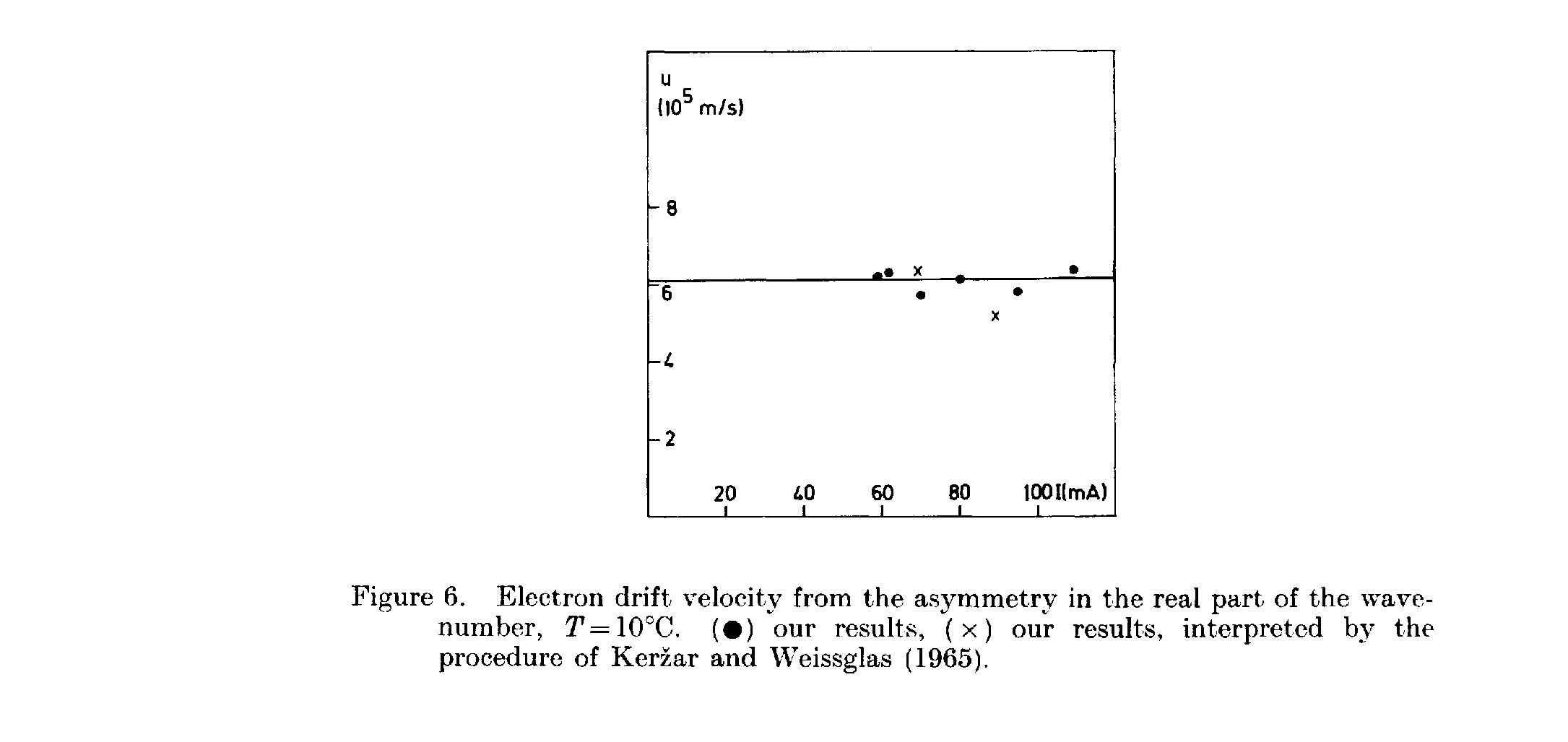
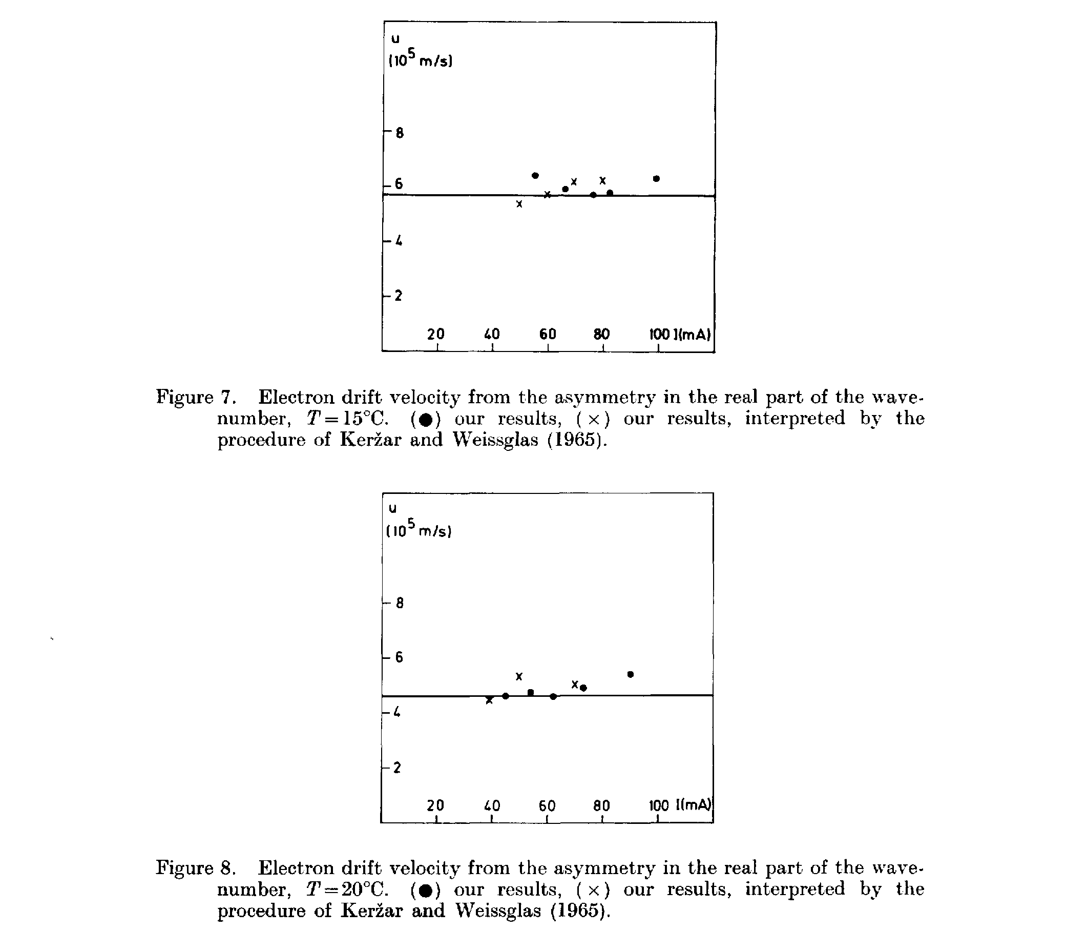
Regarding actual data reduction, the ratio can be found from the Brillouin diagrams (Figs. 3, 4 and 5) by deriving the wavenumber of the plasma at rest as the arithmetic mean of the and :. To avoid the numerical differentiation implied by , curves of the type were fitted to the experimental data and these are shown as solid lines in Figs. 3, 4 and 5. The values of the constants are given in Table 3, for the three temperatures of the mercury pool. The drag coefficient is obtained directly from . The drift velocity follows from (5) and is plotted in Figs. 6, 7 and 8 using the data summarized in Table 4. The mean value of drift velocity is at 10°C, at 15°C, at 20°C. The standard deviation from the mean is of the order of 10%. The plasma frequency was determined from probe measurements which agreed with density data quoted in Ilić and Aničin (1970).
[TABLE]
| 110 | 1.55 | 6.3 |
|---|
134 Β. A. Anicin and V. M. Babović
The determination of electron drift velocity based on electron plasma wave experiments confirms that the Lorentz expression, eqn. (6), for the drag coefficient, i.e. the Fresnel expression, involving only the first two terms in eqn. (6) is not applicable to highly dispersive media and wave modes. The experimental values of the drag coefficient are between 1-5 and 2-8. It seems that a gaseous plasma has certain advantages over substances used classically in this important problem of the optics of moving media, such as high drift velocity and dispersion.
4. Electron drift velocity from the asymmetry in wave amplitudes
The initial amplitudes of the two waves excited by the launcher are markedly different. The difference is measurable several centimetres from the launcher and cannot be confused with attenuation (which is observable over the whole length of the guide). Unlike attenuation effects, which are masked by phase scrambling effects, amplitude asymmetry can be correctly monitored with a sampling oscilloscope.
We assume that the difference in amplitudes stems from the difference in the rest frame of the electron gas. That the wave amplitude is indeed a sensitive function of frequency can be proved analytically (Babović and Aničin 1975, Aničin et al. 1972) if the launching antenna is of sufficiently simple geometry and this was done by Babović and Anicin (1975) for an electric dipole at the tube axis and by Anicin et al. (1972) for a circular slot exciter concentric with the tube.
The initial wave amplitude is defined in Fig. 2, where A~+~ denotes the downstream wave amplitude and A_ denotes the upstream wave amplitude. The Doppler shift in the rest frame of the electrons yields the following amplitudes
dA
A,=A(a>-ku)~A(aj)-ku-z- (9)
Όω
A_ = A(o) + ku)czA(a>) + ku --- (10)
COJ
which gives
_ A_-A~+~
^U^~2k(dAlda>)
Wave determination oj electron drift velocities in positive columns 135
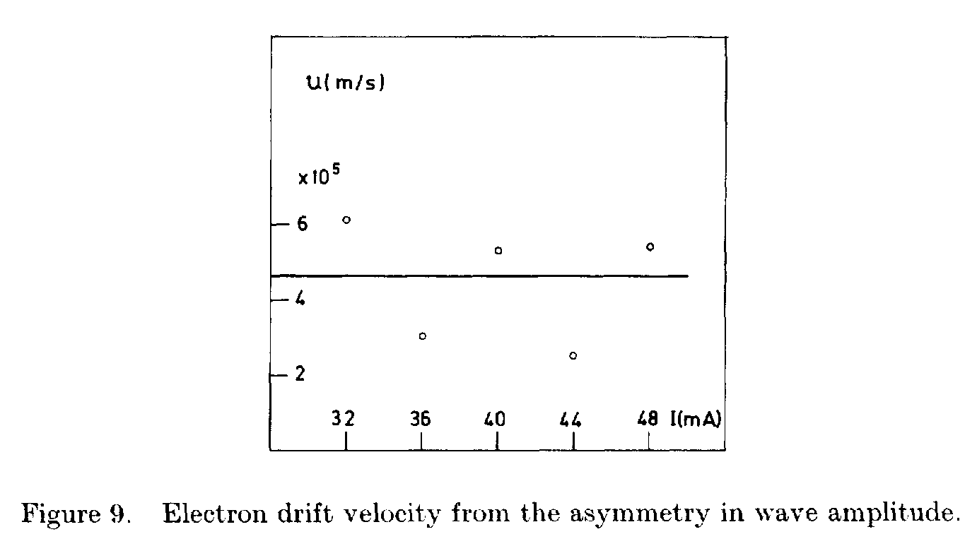
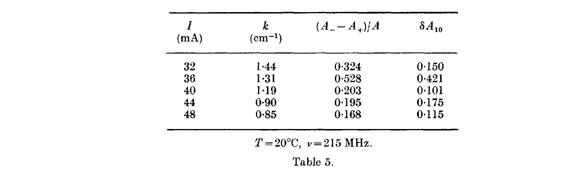
where k = (k~+~ +k_)j2 and A=(A+ + A_)J2. An efficient way to determine the derivative dA/doj can be based 011 the use of amplitude modulation and a spectrum analyser, where the two sidebands appear with different amplitudes. The actual measurements were carried out at two cw frequencies, and the difference 8A (dA/cw~8A/2tt), Ω = 2ττ · 5x 10« s^^1^) measured. The launcher voltage was kept constant at the two frequencies with a VHF voltmeter and a check was run to see whether the launcher system has resonances in the relevant frequency range (215 ±5 MHz) in the absence of the plasma. The results are summarized in Table 5. A graphical presentation is given in Fig. 9 where the results are contrasted with the drift velocity (solid line) derived from arc current. The mean value of the drift velocity from amplitude asymmetry is 4-4 χ 10^5^ m/s at 0-161 Pa but the maximum scatter of the data reaches 40% and is in fact much larger than with the method based on the non-reciprocity of dispersive characteristics of the drifting plasma. Having in mind that the derivative δ^4/9ω can be determined by much more refined procedures such as the use of amplitude modulation and spectrum analysis, and that the difference A~+~ --- A_ can be determined more directly, it is believed that the method can be greatly improved.
REFERENCES
ANIČIN, Β. Α., and BABOVIĆ, V. M., 1974, Proc. 1th Yugoslav Symp. Phys. Ion. Gases,
Rovinj, p. 185 ; 1975, Fizika, 7, 71. ANIČIN, Β. Α., BABOVIĆ, B. M., and ŠULIĆ, D. M., 1973, Proc. llth Int. Conf. Phen.
Ion. Gases, Prague, p. 357. ANIČIN, Β. Α., BABOVIĆ, V. M., and LONNGREN, K. E., 1972, J. Plasma Phys., 7,
403. BABOVIĆ, V. M., and ANIČIN, Β. Α., 1975, Proc. 12th Int. Conf. Phen. Ion. Gases,
Eindhoven, p. 294. FRANKFURT, U. I., and FRENK, A. M., 1972, Optics of Moving Bodies (in Russian).
(Moscow : Nauka).
TLIĆ, D. Β., and ANIČIN, Β. Α., 1970, Int. J. Electron., 28, 41. KERŽAR, Β., and WEISSGLAS, P., 1965, Electronics Lett., 1, 43. LORENTZ, H. A., 1906, Versuch einer Theorie der elektrischen und optischen Erschein-
ungen in bewegten Korpern (Leipzig : B. G. Teubner). TRIVELPIECE, A. W., and GOULD, R. W., 1959, J. appl. Phys., 30, 1784.
Footnotes
-
Received 15 November 1976.
Faculty of Mechanical Engineering, University of Belgrade. Belgrade. Yugoslavia.
Boris Kidrič Institute of Nuclear Sciences, Belgrade, Yugoslavia. ↩